STEP1 -> Smart BMS Wi-Fi accessory CONFIGURATION
NOTE: from SW release 2.0.6 ( Daly or JK ) the Smart BMS WiFi accessory starts as Access Point after Restore to factory.
with your PC, SCAN for WiFi Access point and connect to :
SSID : “dalyBMSWiFi.com” or “SmartBMS.it” (depending on your fw version )
PWD: “123456789”
You will be assigned an address on the IP range 192.168.0.x
When you are WiFi connected , go to url: http://192.168.0.1
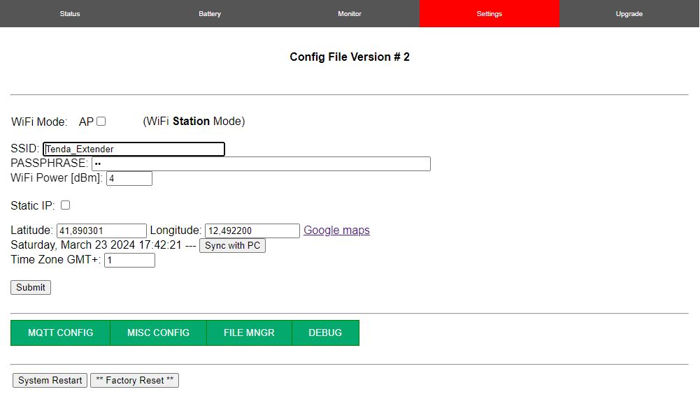
On the “Settings” page : ( username “admin” , password “admin!” )
NOTE: password is “admin!” with a final exclamation mark “!”
1- Remove AP checkmark
2- Add your WiFi Network SSID and PassPhrase
3- Customize your Solar Plant GEO Coordinates to get the right Clock and Time Zone.
-> SUBMIT to apply the new changes.
-> SYSTEM RESTART the dongle to let your changes be effective
SEE SCRENSHOT HEREUNDER
NOTE: Setting page is password protected:
default username “admin” , default password “admin!“
NOTE: Username and Password can be customized ONLY via AT commands.
NOTE: if you change from AP ( default ) to Station mode, you need to verify which IP address is assigned to the dongle .
Follow one or more of the hereunder steps:
1- on your browser type http://smartbms.local:6789 ( from rel 2.0.7 )
2- on Windows/Linux console type: ping smartbms or ping smartbms.local
3- from the AT Serial Console you can verify which IP has been assigned
4- from your Router webpages you can verify your dongle IP
NOTE:
-if hostname “smartbms” does not work try with “smartbms.local“
–Windows support also http://smartbms:6789
-iOS supports ONLY http://smartbms.local:6789
-Android , only latest versions support mDNS to resolve “smartbms.local” , if you have an old version the quicker way to check the dongle IP is to open the “AT USB command”
- NOTE!!! if you were wrong entering the WiFi AP Credentials you MUST to switch back the dongle to AP mode OR use the AT USB Command Mode to recover.
1- from SW release 2.1.3 , Push the Reset button 3 times following EXACTLY the instructions:
– After each press – YOU MUST WAIT – about 5 seconds till the BLUE LED blink very quicly . This is the moment to Press AGAIN the RESET BUTTON. Repeat this 3 Times – dongle will be back in Access point Mode.
NOTE: when dongle is in AP mode, blue led blinks slowly
NOTE: if you Repeat this procedure 6 times, you restore the dongle to Factory default
NOTE: Last less than 1 minute between resets otherwise the reset counter is reset .
2- Via AT Commands:
Either you fix SSID and Password
OR you restore to Factory default to let the dongle to re-start in AP mode
- You can use any hyperterminal – I prefer to use “Tera Term”
( Tera Term ZIP rel 4.106 download from here ) - connect the Smart BMS Wi-Fi accessory via a USB data-cable to your PC
- discover which COM/TTY port is has been assigned
NOTE: if your operating system does not assign any COM/TTY port maybe sw drivers are not installed. GO to troubleshooting page to find drivers and instructions how to install - Setup the Serial port: 57600,8,N,1
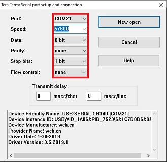
- Select Local echo and set New-line->Transmit as CR+LF
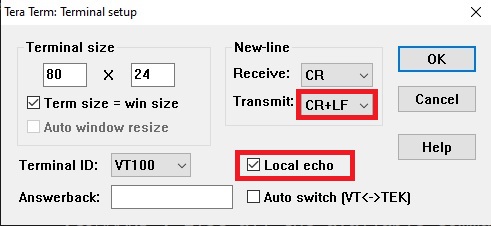
- RESET Smart BMS WI-FI accessory by pressing the button on the left as shown on the following image
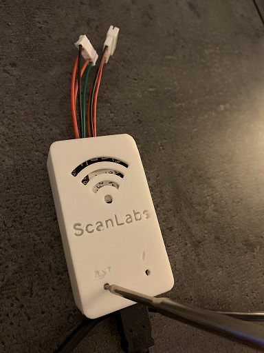
- After few seconds you will see the message: “Init completed!”
- type AT+CMD + ENTER to access to the list of all AT commands
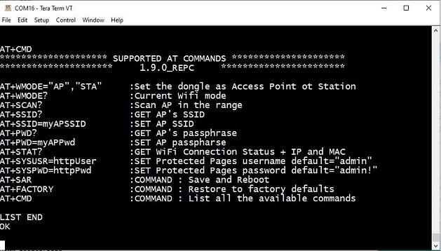
- SUGGESTED PROCEDURE
- AT+SCAN? -> to scan all the Access Points in the range . If you don’t see your AP may be it has a weak signal or it is set on 5Ghz . Smart BMS Wi-Fi accessory supports 2.4Ghz AP only
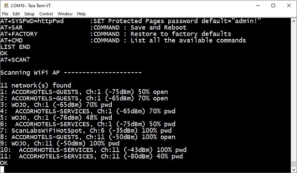
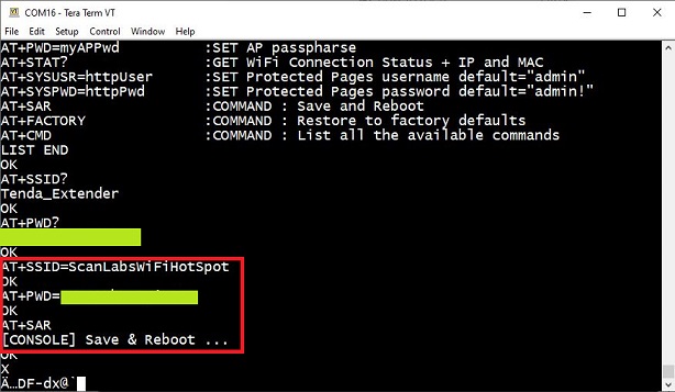
- AT+SSID=myAccessPointPreferredNetwork
- AT+SSID? -> check you entered the right AP name
- AT+PWD=myAccessPointPassphrase
- AT+PWD? -> check you entered the right Passphrase
- AT+WMODE=STA -> to set dongle as Client wifi and save and reboot
- WHEN the dongle is ready for commands check the connection status
- AT+STAT? -> if Smart BMS Wi-Fi accessory reports is connected, take note of the IP address assigned
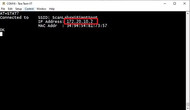
- open your preferred browser , type the IP you have just got assigned.
- ADD the needed PORT to Smart BMS Wi-Fi accessory: 6789
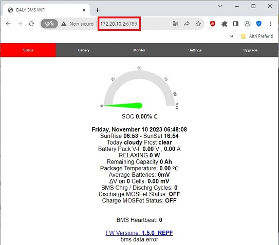
- Now the the Smart BMS Wi-Fi accessory is connected to your AP and you have the IP assigned, it’s time to unplug from USB and wiring to BMS -> go to next tab
NOTE 1: Smart BMS Wi-Fi accessory is still not connected to BMS -> you will get the message “bms data error”
NOTE 2: If you want to access to the Smart BMS Wi-Fi accessory from outside your home network you need to create a PORT forwarding rule on your router for ports 6789 and 6790** ( **optional – only if you use PCMaster passthrough feature )
*this is an independent accessory compatible with “DALY or JK Smart BMS”
STEP2 -> Smart BMS Wi-Fi accessory WIRING
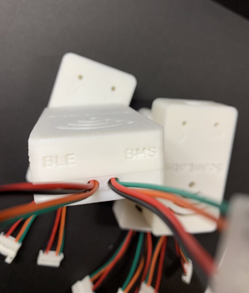
- Smart BMS Wi-Fi accessory exposes 1 or 2 connectors on the TOP + usb on the Bottom
- TOP ( see image below )
- to “BLE” : OPTIONAL
this is a female 6 pin connector which you can connect your DALY* Smart BMS Bluetooth LE accessory - to “BMS”: MANDATORY
this is a male connector that goes into the :
– DALY* / Hi Smart BMS Serial Port (UART / RS232) , the same where today you connect your DALY* Smart Bluetooth LE accessory
- to “BLE” : OPTIONAL
- BOTTOM
- “USB“: MANDATORY if your dongle has NOT an internal DCDC
the Smart BMS dongle is powered by the USB Port, this is a mandatory connection unless your dongle has an integrated DCDC.
If your dongle has the internal DCDC it’s a MUST do don’t connect the dongle to the BMS and the USB at the same time. Use USB ONLY for configuration when the dongle is NOT connected to the BMS.
You can use a standard smartphone micro USB 5V power supply
- “USB“: MANDATORY if your dongle has NOT an internal DCDC
- NOTE: unplug the USB power while wiring the DALY* Smart BMS Wi-Fi accessory – when all connections are made, power the accessory via USB
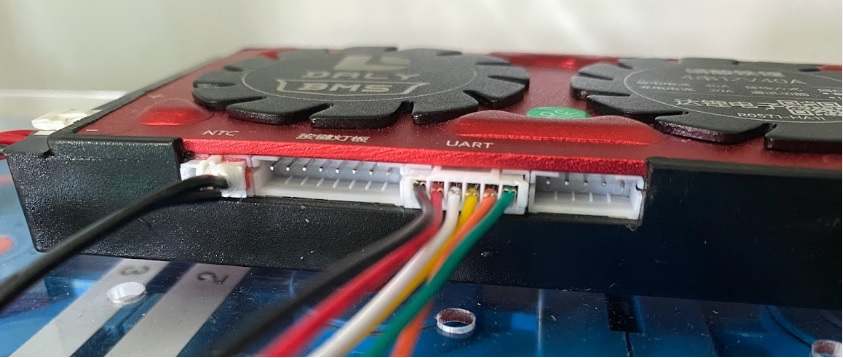
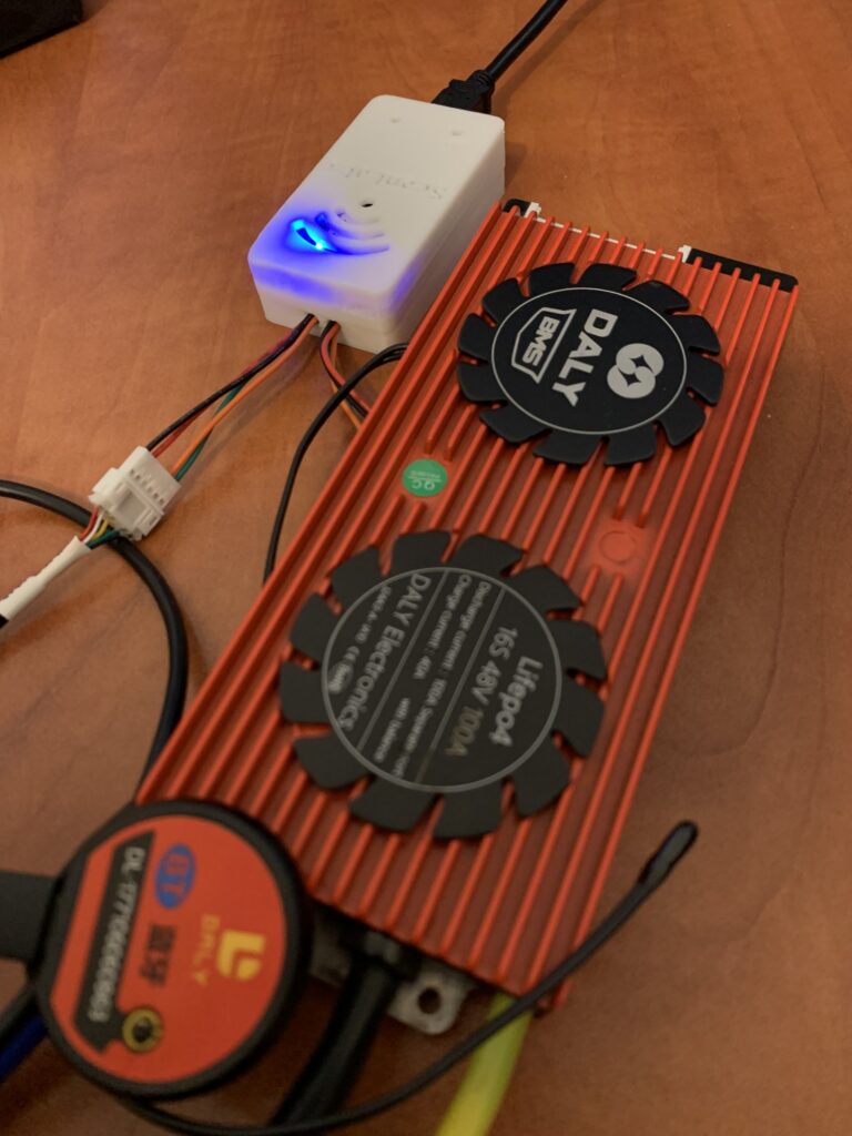
*this is an independent accessory compatible with “DALY Smart BMS”
Hi BMS is the entry level version of DALY! follow the same instructions provided for Daly
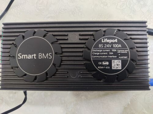
List of supported JK is HERE
- Smart BMS Wi-Fi accessory exposes 1 on the TOP + usb on the Bottom
- “USB“: MANDATORY
the Smart BMS is powered by the USB Port, this is a mandatory connection – you can use a smartphone little power supply. - to “BMS”: MANDATORY
this is a male connector that goes into the :
– JK GPS ( 4 wire JST port )
- “USB“: MANDATORY
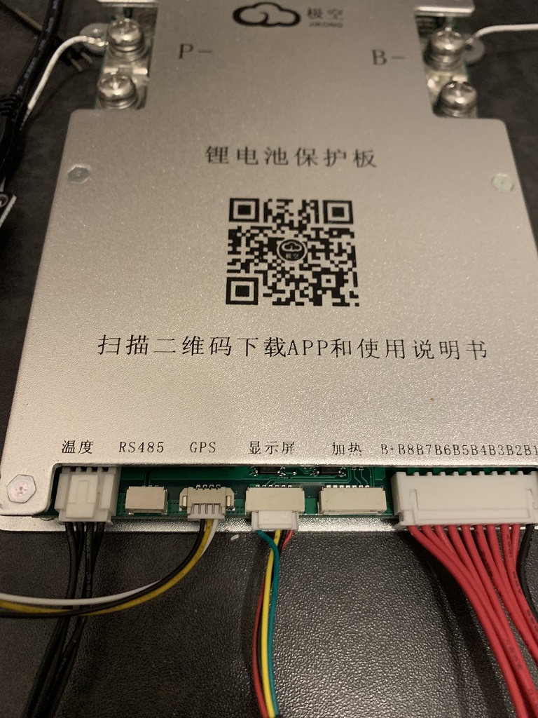
NOTE: unplug the USB power while wiring the ScanLabs Smart BMS Wi-Fi accessory – when all connections are made, power the accessory via USB
STEP3 -> Smart BMS Wi-Fi accessory BROWSING WEB PAGES
you can reach Dongle’s webpages at:
http://smartbms.local:6789 ( STATION MODE )
http://192.168.0.1 ( Access Point MODE )
Welcome page is as follow – Simple view of your BMS
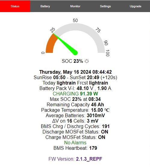
NOTE – FIRST BMS data are aquired 30s after the power up
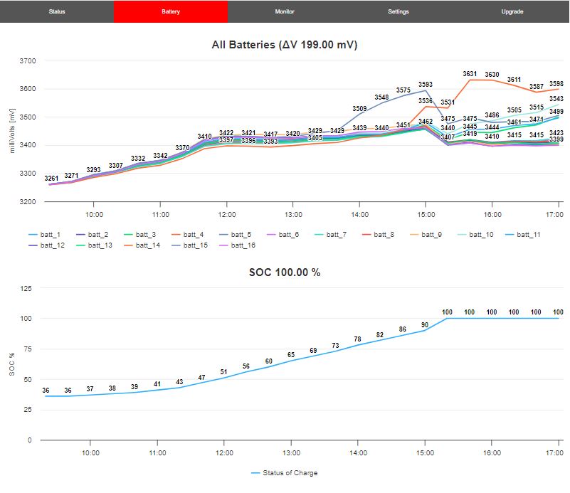
- Go to the “BATTERY” tab to watch your batteries over the rolling 24h period
you can isolate each battery simply clicking on the ” batt_ ” title .
you can ZOOM IN/OUT as usual to focus on critical moments
NOTE: as you can see on the image below – is evident that on this pack batt_14 has less capacity than all the other batteries and it is somehow limiting the whole capacity of the pack
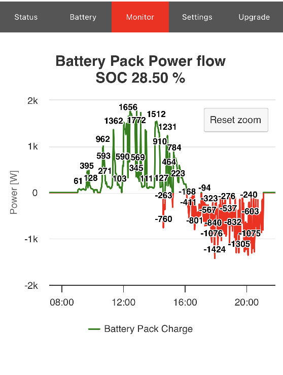
- GO to the “MONITOR” tab to watch the CHARGING-DISCARGING phases of your battery pack over the 24h rolling period
*this is an independent accessory compatible with “DALY/Hi and JK Smart BMS”
in this section you find instructions for all the supported advanced services implemented and available on the dongle
STEP4.1 -> Smart BMS Wi-Fi accessory MQTT Settings
NOTE: Step 1 and 2 are mandatory to setup MQTT on the dongle , then you select how you want to access to the info published.
>> FULL GUIDE ITALIANO <<
english guide coming soon 😉
FIRST you need to create an account to an MQTT Broker .
if you use HOME ASSISTANT, Mosquitto (w or w/ TLS ) this is your way.
if you want to QUICK test MQTT you can use MQTTHQ broker
HIVEMQ Broker as example – different steps may be needed with other MQTT Broker
STEP 4.1.1 -> Create a free MQTT Account on HiveMQ
- define the username and password and click on ADD.
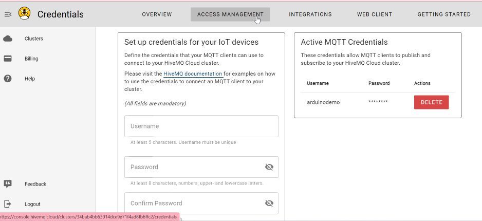
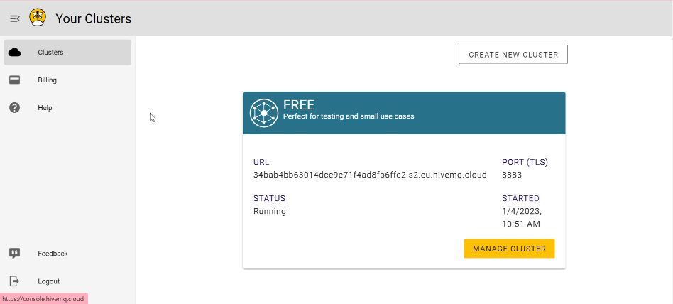
- Clicking on ‘Clusters’ , get the cluster URL, port number, and access credentials for use in DALY* Smart BMS Wi-Fi accessory config page
STEP4.2.1 -> Setup DALY* / Hi / JK Smart BMS Wi-Fi accessory with HiveMQ credentials
- on page “SETTINGS” -> “MQTT CONFIG”
- enter the HiveMQ credentials you prepared on STEP 4.1.1
- Select whether you use TLS or not
- NOTE: from rel 2.0.5 onward NO reboot is needed
- SUBMIT
NOTE: “MQTT Client ID” must be unique on your devices
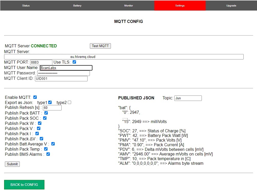
- Enable MQTT by clicking on the “Enable MQTT” check button
- Refresh time is how often the set of parameters is published in seconds
- Select if you want to export JSON type1 or type2 ( effect how batteries are published )
if type1 and type2 are unchecked , a flat publish is performed - On the right view, customize the main JSON MQTT Topic, “Jsn” by default
- Select which parameter you want to publish
- A dinamic view on the right panel shows what you are publishing
NOTE: on the right view the MQTT payload published .
it is strongly suggested to have a local MQTT client subscribed to the same topics to verify what is happening on your system.
MQTTX for Windows is suggested :

STEP4.1.3 -> Setup an MQTT Subscriber – you can use your Mobile Phone or PC Client
you can use many APPs – for testing I have used :
1- “IoT ONOFF” available for both iOS and Android
2- “IoT MQTT Panel” for both iOS and Android
>> FULL GUIDE ITALIANO <<

IoT ONOFF configuration
Following images are taken from an iOS mobile.
- Tap on the 3 bars on the top left and then “Settings” on the bottom left -> chose “Configuration”
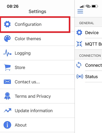
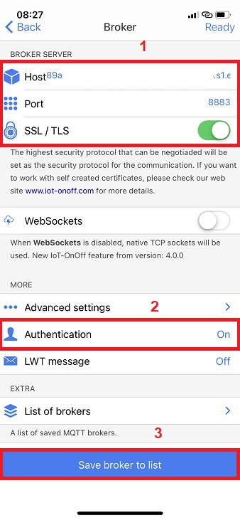
- Tap on “MQTT Broker”
- on Host and Port copy the HiveMQ credentials and Port
- enable SSL/TLS
- go to “Athentication” and add your credentials sets on HiveMQ
- add User and Password + ENABLE Authentication
- SAVE Broker to List
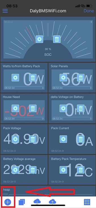
- ADD a NEW Widget
- Select the best one for your visualization
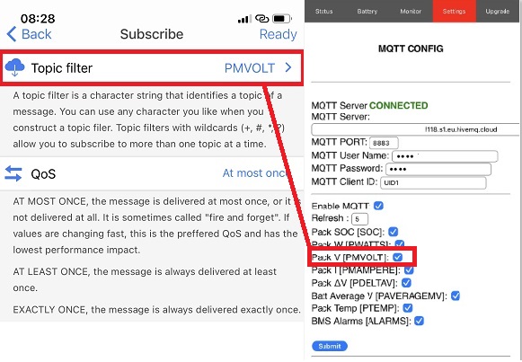
- configure the widget e.g. let’s link Pack Voltage [PVOLT]
- 1- add the name you will see on the DashBoard
- 2- go to SubScribe tab to link widget to MQTT published parameter
- 3- Set MIN/MAX/format and unit
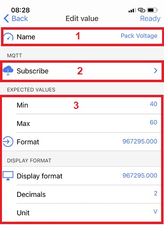
NOTE: On the SubScribe page you MUST use the same names exported on the Daly Smart BMS Wi-Fi Accessory MQTT Page. In this example PMVOLT
- Repeat these steps for all the parameters you may want to monitor
IoT MQTT Panel for Android and IoS
>> FULL GUIDE ITALIANO <<
load this IoTMqttPanelTEST.json on the app to monitor my plant 🙂
Following images are taken from an Android on A50
From Sw release 2.0.7 – after you have configured MQTT broker ( see steps before ) you can export a JSON file that includes ALL the needed config : Broker config + DashBoard
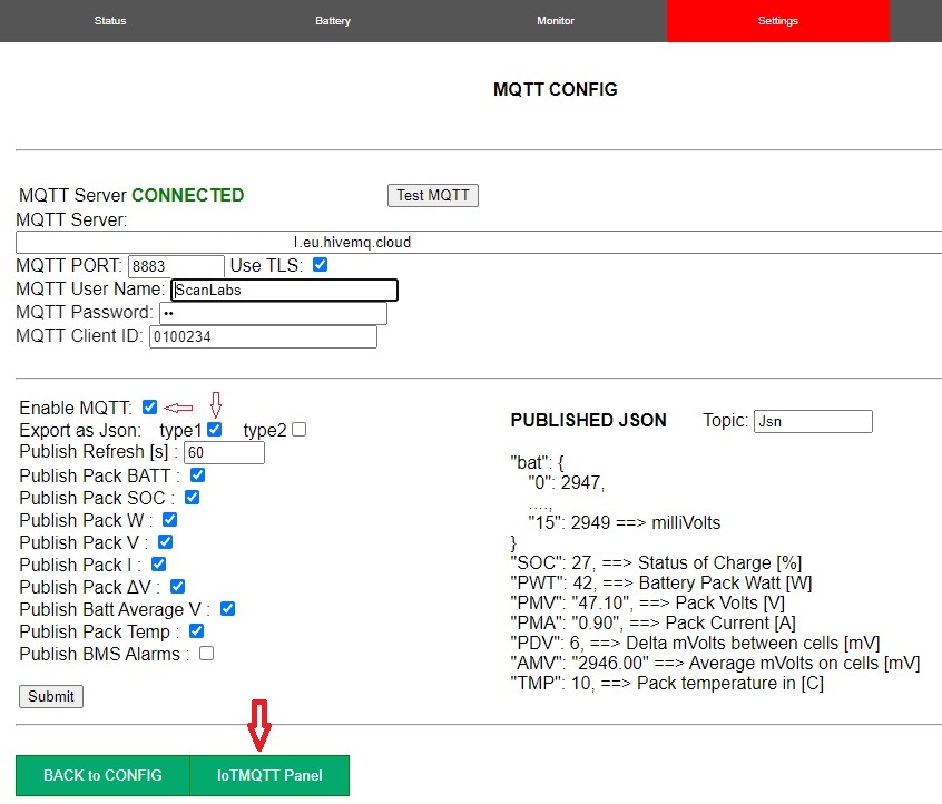
from MQTT webpage, AFTER you have configured all the settings and broker … tap on IoTMQTTPanel and export the json file.
NOTE 1: if you do it on the target modile, the json file is already on your mobile 🙂
NOTE 2: Export MQTT as JSON Type 1
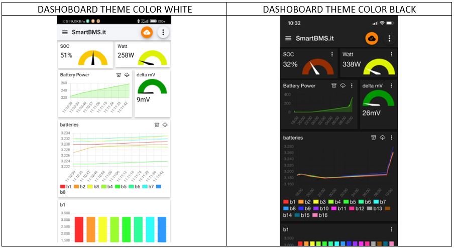
From IoT MQTT Panel App, go to “RESTORE” and select the JSON file created .
The results is something like this 🙂
4.1.4 as example download MQTTX


4.5.1 – MQTTHQ is a free MQTT Broker
It looks it does not support TLS or JSON MQTT payload.
Test your MQTT ScanLabs dongle following the steps :
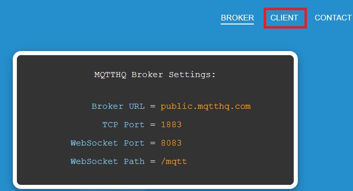
on MQTTHQ webpage ,
1- take note of the credentials needed to publish here
2- Configure the Dongle
3- go to CLIENT tab and subscribe for topics
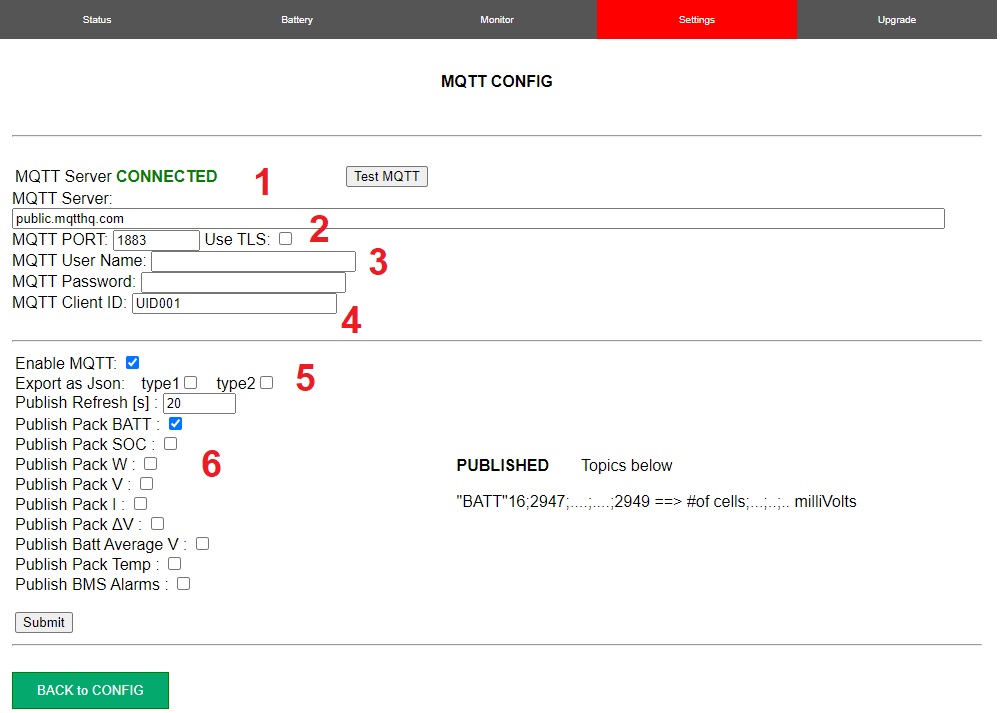
4.5.2 – Configure the dongle following steps 1-2-3-5 as reported on the image below plus the following
4- “MQTT Client ID” chose something unique !
6- Chose at least one parameter for the moment. eg. “BATT”
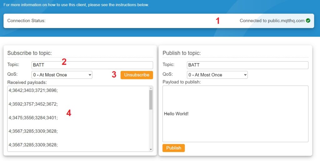
3- Configure MQTTHQ MQTT WebClient to subscribe to “BATT”
3.1 Connect to the Broker
3.2 edit Topic
3.3 Subscribe to the Topic
3.4 Wait for data sent by the dongle ( in the example 4 batts followed by mV )
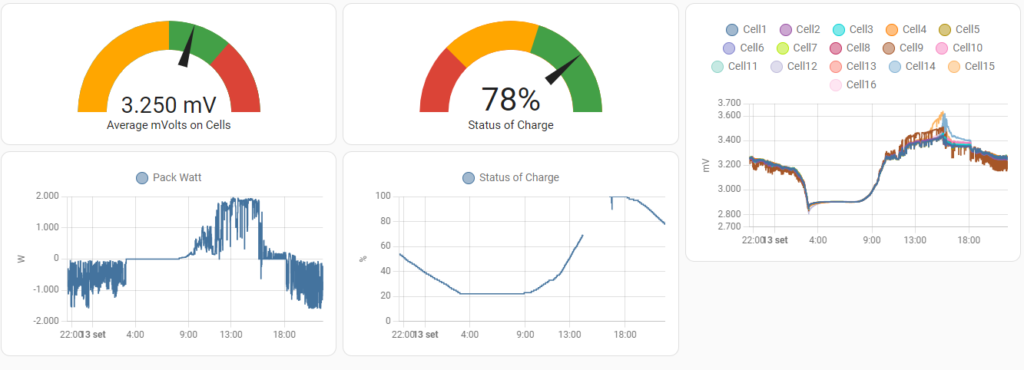
STEP 1: Install Mosquitto MQTT server on your Home Assistant server
STEP 2: Optional: Create a new account on HA . You will use it to setup the MQTT access Credentials on dongle .
STEP 3: Edit “/homeassistant/configuration.yaml” and add the configuration below
NOTE 1: Instead of “Jsn” use the topic Name you have selected on the MQTT dongle page
STEP 4: Setup the dongle MQTT Client to connect to the Mosquitto MQTT Server on your Home Assistant ( IP address is the same as your HA webpage , for ports depend who you setup Mosquitto )
STEP 5: on dongle MQTT, set to Export MQTT as JSON Type 2
STEP 6: on dongle MQTT, Flag all the BMS parameters to be exported
YALM config kindly provided by Rolf from Germany:
mqtt:
  sensor:
    - name: Status of Charge
      unique_id: status_of_charge
      state_topic: "Jsn"
      unit_of_measurement: "%"
      value_template: "{{ value_json.SOC }}"

    - name: Average mVolts on Cells
      unique_id: average_mvolts_on_cells
      state_topic: "Jsn"
      unit_of_measurement: "mV"
      value_template: "{{ value_json.AMV }}"

    - name: Pack Volts
      unique_id: pack_volts
      state_topic: "Jsn"
      unit_of_measurement: "V"
      value_template: "{{ value_json.PMV }}"

    - name: Pack Watt
      unique_id: pack_watt
      state_topic: "Jsn"
      unit_of_measurement: "W"
      value_template: "{{ value_json.PWT }}"

    - name: Pack Amps
      unique_id: pack_amps
      state_topic: "Jsn"
      unit_of_measurement: "A"
      value_template: "{{ value_json.PMA }}"

    - name: Delta mVolts between Cells
      unique_id: delta_mvolts_between_cells
      state_topic: "Jsn"
      unit_of_measurement: "mV"
      value_template: "{{ value_json.PDV }}"

    - name: Temperature
      unique_id: temperature
      state_topic: "Jsn"
      unit_of_measurement: "°C"
      value_template: "{{ value_json.TMP }}"

    - name: Cell1
      unique_id: cell1
      state_topic: "Jsn"
      unit_of_measurement: "mV"
      value_template: "{{ value_json.b0 }}"

    - name: Cell2
      unique_id: cell2
      state_topic: "Jsn"
      unit_of_measurement: "mV"
      value_template: "{{ value_json.b1 }}"

    - name: Cell3
      unique_id: cell3
      state_topic: "Jsn"
      unit_of_measurement: "mV"
      value_template: "{{ value_json.b2 }}"

    - name: Cell4
      unique_id: cell4
      state_topic: "Jsn"
      unit_of_measurement: "mV"
      value_template: "{{ value_json.b3 }}"

    - name: Cell5
      unique_id: cell5
      state_topic: "Jsn"
      unit_of_measurement: "mV"
      value_template: "{{ value_json.b4 }}"

    - name: Cell6
      unique_id: cell6
      state_topic: "Jsn"
      unit_of_measurement: "mV"
      value_template: "{{ value_json.b5 }}"

    - name: Cell7
      unique_id: cell7
      state_topic: "Jsn"
      unit_of_measurement: "mV"
      value_template: "{{ value_json.b6 }}"

    - name: Cell8
      unique_id: cell8
      state_topic: "Jsn"
      unit_of_measurement: "mV"
      value_template: "{{ value_json.b7 }}"

    - name: Cell9
      unique_id: cell9
      state_topic: "Jsn"
      unit_of_measurement: "mV"
      value_template: "{{ value_json.b8 }}"

    - name: Cell10
      unique_id: cell10
      state_topic: "Jsn"
      unit_of_measurement: "mV"
      value_template: "{{ value_json.b9 }}"

    - name: Cell11
      unique_id: cell11
      state_topic: "Jsn"
      unit_of_measurement: "mV"
      value_template: "{{ value_json.b10 }}"

    - name: Cell12
      unique_id: cell12
      state_topic: "Jsn"
      unit_of_measurement: "mV"
      value_template: "{{ value_json.b11 }}"

    - name: Cell13
      unique_id: cell13
      state_topic: "Jsn"
      unit_of_measurement: "mV"
      value_template: "{{ value_json.b12 }}"

    - name: Cell14
      unique_id: cell14
      state_topic: "Jsn"
      unit_of_measurement: "mV"
      value_template: "{{ value_json.b13 }}"

    - name: Cell15
      unique_id: cell15
      state_topic: "Jsn"
      unit_of_measurement: "mV"
      value_template: "{{ value_json.b14 }}"

    - name: Cell16
      unique_id: cell16
      state_topic: "Jsn"
      unit_of_measurement: "mV"
      value_template: "{{ value_json.b15 }}"
from fw rel 2.1.0 MODBUS TCP Server on port 502 has been added
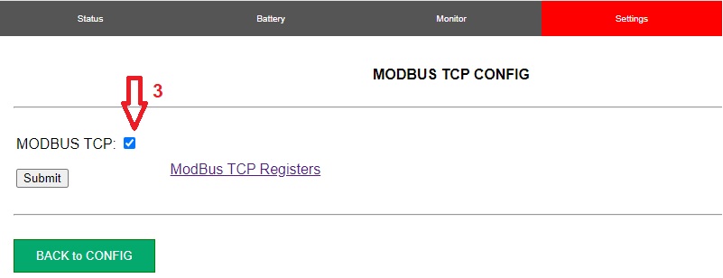
4.2 MODBUS TCP Server is not active by default – enable it
GO to “Settings” -> “MODBUS CONFIG“
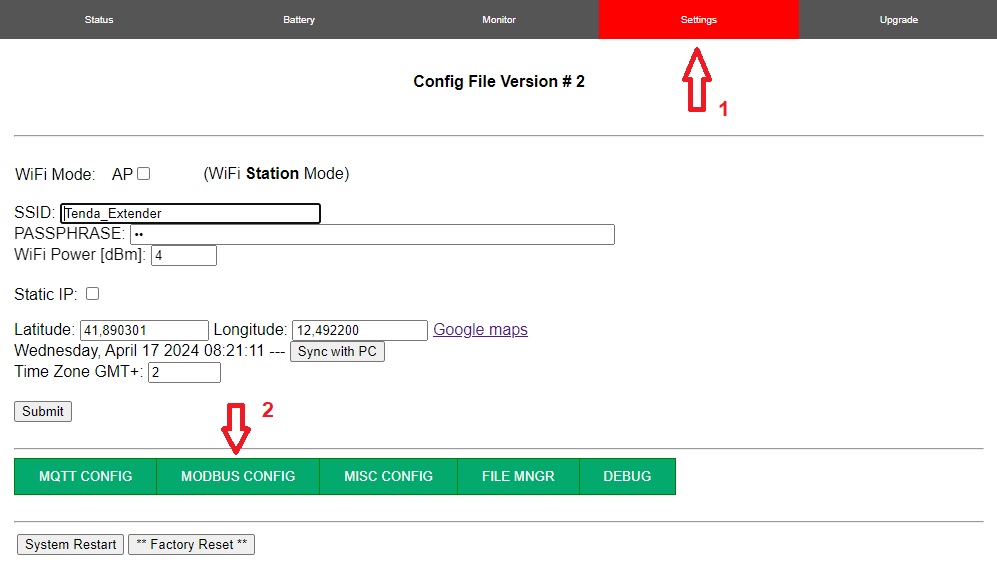
5.2 Enable MODBUS TCP Server
Click on the check button and “Submit” (no reboot needed )
NOTE : due to limited resources it is NOT suggested to have MODBUS TCP and MQTT working in Parallel
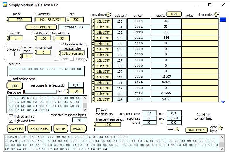
5.3 How to TEST MODBUS TCP Server with PC?
Any Standard MODBUS TCP Client is fine – for quick test you can use “Simply MODBUS TCP Client”
5.4 How to TEST MODBUS TCP Server with SmartPhone ?
- 1- Install “Virtuino” APP on your mobile
- 2- download THIS configuration file
- 3- Open the Virtuino App -> “My projects” -> “Import project” -> select the “.vrt7” configuration file provided
- 4- from the three dots -> “My Connection or Devices” -> “Modbus TCP/IP” -> URL -> customize with your LAN or WAN IP address .
5.4 Current release 2.1.0 support the following Hardare Regs – other will be implemented soon
Hardware REG ( Function 03 ) – BASE address 100 – Server PORT 502
| Function | Unit | Offset | Type | Description |
| SOC | % | 0 | unsigned int16 | Status of Charge |
| Pack Volts | V | 1 | unsigned int16 | Battery Pack Volts |
| Pack Amps | A | 2 | signed int16 | Battery Pack Amps |
| Pack Power | W | 3 | signed int16 | Battery Pack Power |
| Pack Volts | V | 10 | Float Little endian | Battery Pack Volts |
| Pack Amps | A | 12 | Float Little endian | Battery Pack Amps |
| Pack Power | W | 14 | Float Little endian | Battery Pack Power |
| Battery 1 | mV | 20 | unsigned int16 | Battery 1 mV |
| Battery 2 | mV | 21 | unsigned int16 | Battery 2 mV |
| … | mV | … | … | … |
| Battery 16 | mV | 35 | unsigned int16 | Battery 3 mV |
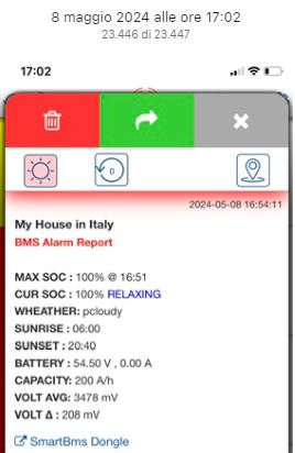
PUSHSAFER is a third party service meant to receive push notification on mobile phones or computers .
From fw release 2.1.1, ScanLabs WiFi Dongle is enhanced with this new service aim to send push notifications in one or more of the following conditions:
- Daily Report Sent when SunSut comes
- Daily Report Sent when SunRise comes
- Report when battery reaches 100% SOC
- Report when one or more Alarms is/are detected
Pushsafer it comes with a very interesting offer, as of today 0.99€ for 1000 notifications or 1.99€ for 2200 notifications ! looks nice don’t you ?
For the sake of testing , Pushsafer offers 50 notifications for free, it’s just a matter to create an account – install Pushasafer app on your mobile(s) and or PC(s) – setup the ScanLabs dongle accordingly and you are done.
Let’s follow these steps to enable and test the Pushsafer service
4.3.1 – create your free account on pushsafer.com you will have 50 free push to test the service
4.3.2 – Login, on the main dashboard, copy “YOUR PRIVATE KEY”

4.3.3 – Go to your ScanLabs SmartBMS WiFi Dongle “Settings” web page
1- Select PUSHSAFER Service

4.3.4 – Setup the dongle with Pushsafer credentials ( follow steps 1-5 on the image)
4.3.4.1 Paste your PushSafer “PRIVATE KEY”
4.3.4.2 Setup your friendly message each push will report
4.3.4.3 Select which kind of push you wnat to get every day
4.3.4.4 Enable PUSHSAFER Service
4.3.4.5 SUBMIT the settings

4.3.5 – using the QRCODE and Links offered on the main page of PushSafer.com, install the app on one or more iOS, Android, Windows , Telegram etc ….
login on each instance with the PushSafer credentials you have created

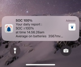
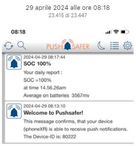
4.3.6 Now you are ready to TEST if a push Notification reaches your device/s

AT THIS POINT YOU SHOUL BE HAPPY 😉
Select which open-project you want to use
Both projects are tested with ESP32-2432S028R Sunton 2.8″ 240*320 CYD Display.
Other display could works ? YES but you need to adjust yourself the dashboard.
MQTT is used to share information between the dongle and the Display.
Each LCD Display can show MORE than one Battery Pack
You can install as many Color Display as you want – no limitations.
openHASP is Light and Great ! … but it does not support MQTT Secure ( TLS)
no way to test it with HiveMQTT for instance.
TASMOTA is a far way more complex and active project.
It needs more HW resources and it works fine with MQTT Secure (TLS)
The dongle can publish MQTT packets for both the display kind at the same time.
STEP4.4.1 -> Smart BMS Wi-Fi accessory PASSTHROUGH Settings
NOTE ! as of today PASSTHROUGH is available only for DALY/Hi .
TWO meanings for passthrough :
- for Smart BMS Bluetooth LE accessory
- for PC-Software like DALY PCMaster.exe or JK JK-BMS-Monitor.exe
- On the SETTINGS -> MISC CONFIG
- ENABLE “BMS Passthrough”
- Push on “Submit”
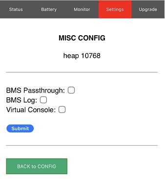
with your DALY* Smart BMS Bluetooth accessory connected to the Wi-Fi accessory you will use the “SMART BMS” app on your mobile as usual.
NOTE: DALY* Smart BMS Wi-Fi accessory does not miracles …. your can use the “SMART BMS” app in the physical range of the Bluetooth radio … 10-20mts as usual!
You may want to SNIFF/LOG all the transactions between the DALY* Smart BMS Bluetooth accessory and BMS
- ON the SETTIGS -> MISC CONFIG
- ENABLE: “BMS Log”
- Push on “Submit”
To watch the LOG go in “SETTINGS -> DEBUG”
DALY* Smart BMS is a Server – it replies to every query/setting the DALY* Smart BMS accessory sends.
On the LOG you may notice each transaction starts with a [TRANSACTION ID] to easily recognize TX-RX sequences
WHAT IS MEANT FOR ?
Want to use your PC Software for DALY or JK to get access to your BMS(s) from wherever you are in the world ?
with “Virtual Console” feature exported by the dongle this is possible !
PCMaster.exe included on the packages, formerly DalyBmsMonitorV1.x.x or now PC Software-2.1.8, is the official DALY PC tool you can use, physically connected to the DALY Smart BMS, to GET and SET all the BMS parameters.
JK-BMS-MONITOR is the official JK PC tool you can use, physically connected to the JK Smart BMS, to GET and SET all the BMS parameters.
Giant limitation of these SW is that you need to go close to the BMS and physically connect to the BMS via and USB adapter.
With “Virtual Console” feature you can simulate a COM port on your PC that is tunneled over Internet up to the Smart BMS Wi-Fi accessory to let you use the PC Software independently on where you are.
HOW TO USE IT :
- On the SETTINGS -> MISC CONFIG
- ENABLE “Virtual Console”
- Push on “Submit”

NOTE: Virtual Console has a 1 minute inactivity timeout . Seconds to timer expiration are shown on the web page.
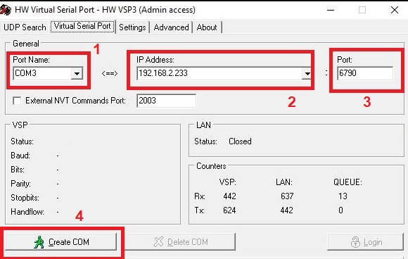
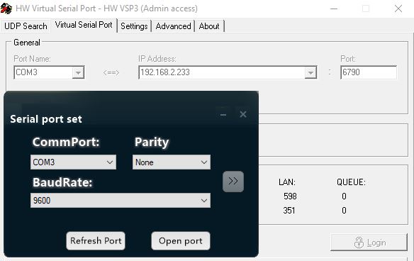
- INSTALL HW Virtual Serial Port – download from here.
- CONFIG the COM over TCP emulator
- 1 – Select the name of the COM port you will use
- 2- Select the IP address of the DALY Smart BMS Wi-Fi accessory ( it could be a local IP or global IP if you created a port forward on your router )
- 3- Set the DALY Smart BMS Wi-Fi Virtual COM port : 6790
- 4- Create the COM
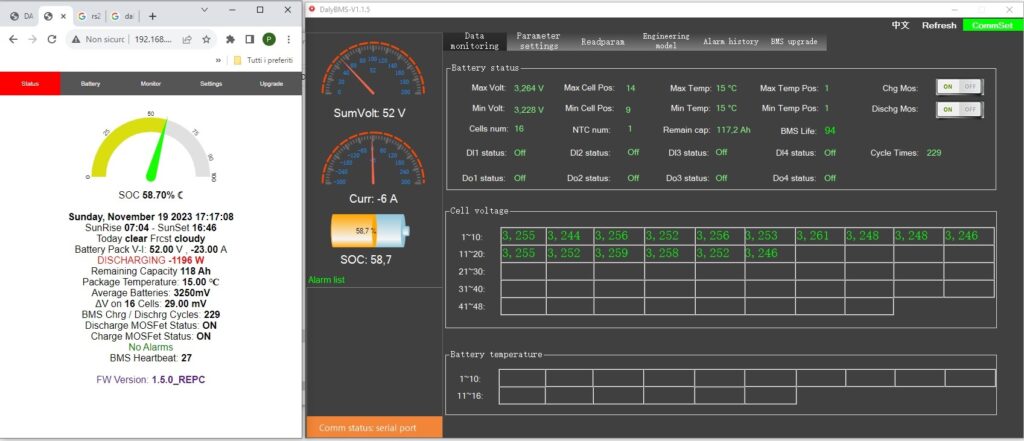
- OPEN PC MASTER SOFTWARE on you PC
- on the up right corner press “ConnectSet”
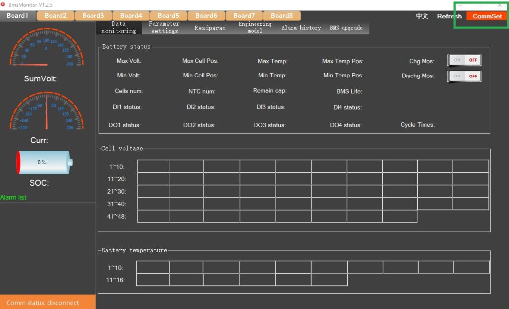
- SETUP THE UART
- on the pop-up window select the SAME COM port you defined on the tunneling SW – PARITY None – Baud Rate 9600
- AT THIS POINT you simply have to ENJOY 🙂
- To CLOSE The connection simply close PC Master , and press “DELETE COM” on the tunneling SW or simply UNCHECK the Virtual Console flag on the web page .
May be you have any further suggestion ? drop a message to me at info@dalybmswifi.com